
 英语
英语 西班牙语
西班牙语 德语
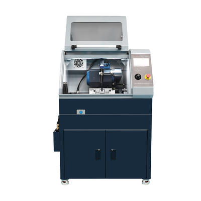
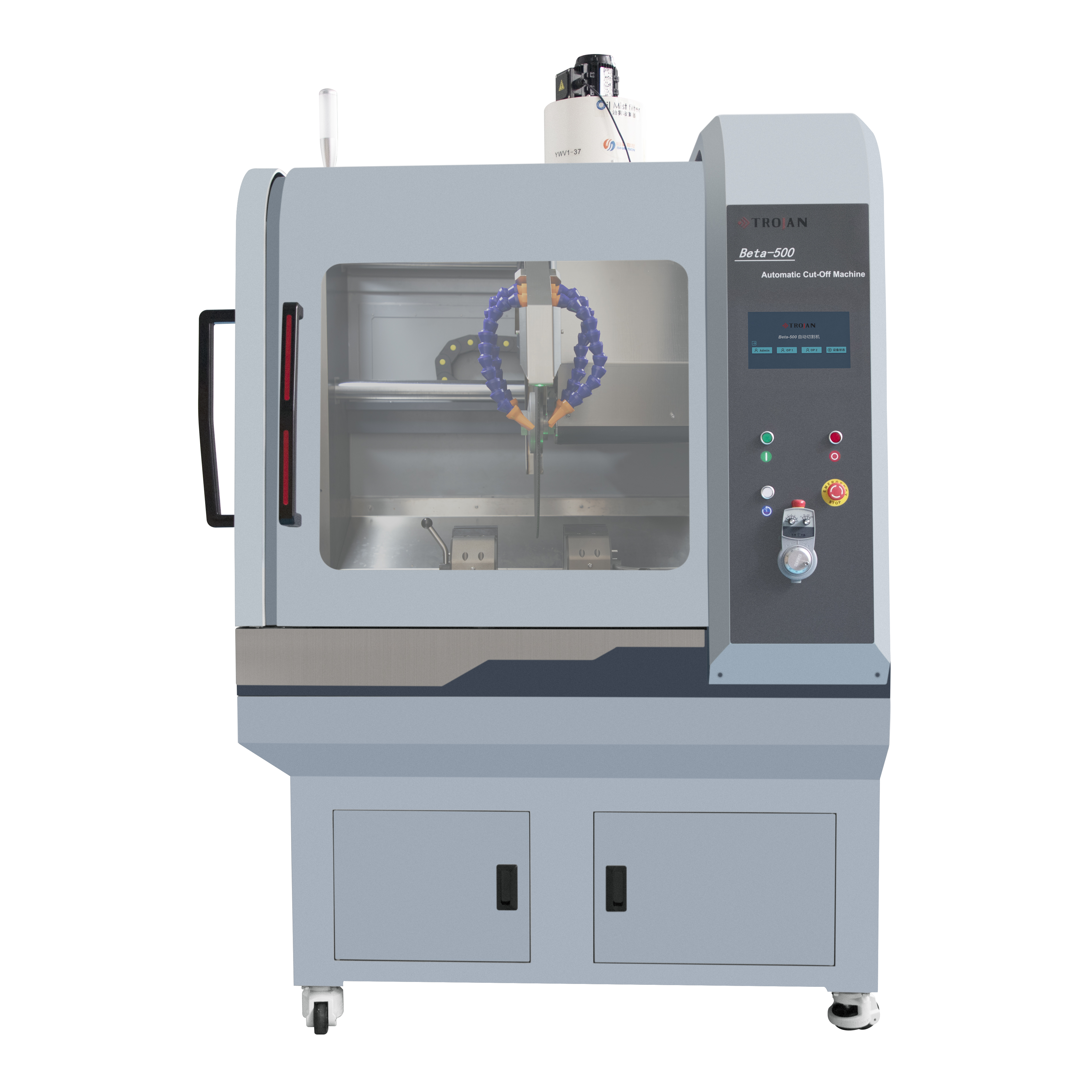
德语Beta-300Pro Automatic Abrasive Sectioning Machine
Beta-300Pro is a fully automatic vertical metallographic cutting machine. It utilizes advanced intel...
We use first- and third-party cookies including other tracking technologies from third party publishers to give you the full functionality of our website, to customize your user experience, perform analytics and deliver personalized advertising on our websites, apps and newsletters across internet and via social media platforms. For that purpose, we collect information about user, browsing patterns and device.
By clicking "Accept All Cookies", you accept this, and agree that we share this information with third parties, such as our advertising partners. If you prefer, you can choose to continue with "Only Required Cookies". But keep in mind that blocking some types of cookies may impact how we can deliver tailored content that you might like.
For more information and to customize your options, click on "Cookie settings". If you want to learn more about cookies and why we use them, visit our Cookie Policy page at any time. Cookie Policy

When a hardness reading has to represent a specific local feature rather than the bulk of the part, microindentation is the method to use. A thin hard coating, a case-hardened layer of 100 µm on a gear, or an individual phase inside a cast metal — these are the kinds of features that a Rockwell or Brinell test would simply measure too deep to capture. A microindentation tester applies a light force to a diamond indenter, leaving a tiny impression that can be measured optically. This article explains how the technique works, where it fits in a metallographic workflow, and which equipment choices matter in practice.
Microindentation is a hardness test that presses a diamond indenter of known geometry into a polished specimen under a controlled force. The load range typically sits between 10 gf and 1000 gf, which produces a small impression that must be measured with a microscope. The two most common indenter geometries are the Vickers square-based pyramid and the elongated Knoop diamond.
For Vickers hardness, the calculation uses the average diagonal length of the square impression:
HV = 1.8544 × F / d²
Where F is the applied force in kgf and d is the average diagonal length in millimetres. Because the impression is small and the measurement depends on optical resolution, the balance between force precision and microscope magnification determines the accuracy of the result.
Measurement of the impression is where microindentation differs most from macro hardness testing. A typical microindentation diagonal might be 20 µm to 200 µm across, so the optical system and its calibration become critical. A digital camera connected to the hardness tester can capture the indentation and automatically measure the diagonals, removing a significant amount of operator judgment. For laboratories running case-depth profiles, automated measurement also speeds up the workflow considerably.
Knoop microindentation works on the same principle but leaves an elongated diamond-shaped impression. The Knoop indenter penetrates to a shallower depth for the same load, which makes it a useful option for very thin coatings and brittle ceramics.
Understanding the position of microindentation among the indentation hardness testing techniques helps you pick the right method for each sample type.
| Test Type | Typical Force Range | Indenter | Primary Application |
|---|---|---|---|
| Macroindentation | 1 kgf and above | Brinell, Rockwell, Vickers | Bulk hardness of large components |
| Microindentation | 10 gf – 1000 gf | Vickers, Knoop | Thin layers, small parts, phase identification |
| Nanoindentation | mN range and below | Berkovich, cube corner | Thin films, mapping of mechanical properties |
Microindentation occupies the practical middle ground. The indentations are large enough to be measured reliably with a standard optical system, yet small enough to target a specific microstructural region. For routine quality control and materials research, this balance is exactly what most metallurgical laboratories need.
Microindentation is used across a wide range of materials. In metals, it verifies case-hardened layers, evaluates individual phases in a microstructure, and measures gradients across welds and surface treatments. In ceramics and hard materials, it checks the quality of coatings and the uniformity of sintered structures. In the biomedical field, microindentation is used to study the stiffness of cortical bone. In geoscience, the technique quantifies the micromechanical behavior of rocks.
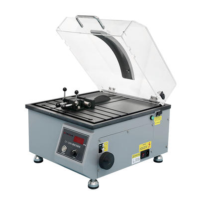
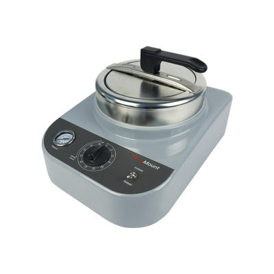
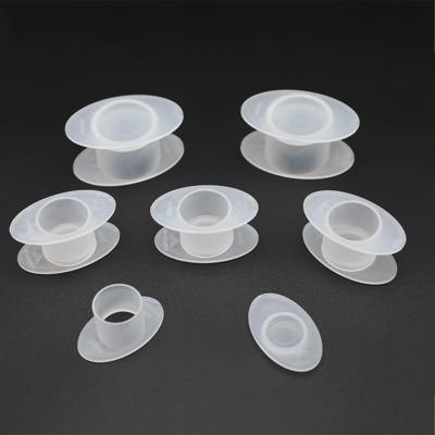
For suppliers of metallographic equipment, the important connection is that microindentation is a downstream step of sample preparation. The same laboratory that cuts, mounts, and polishes specimens for metallographic inspection is the laboratory that uses the hardness tester. This is why equipment selection should be considered together rather than in isolation.
Microindentation results are only as trustworthy as the surface you test. A rough or smeared surface distorts the indentation shape, making the measured diagonal appear longer or shorter than the true value. The standard metallographic preparation sequence applies:
An automatic grinder-polisher such as the alpha610 automatic grinder and polisher helps standardize the preparation cycle. A repeatable surface condition across all specimens reduces the chance that preparation variability will mask genuine hardness differences. For more on the complete workflow, Trojan's sample preparation section describes equipment for every step.
Material type brings specific preparation requirements. A silicon carbide wafer needs a strategy that minimizes edge chipping and cracking, while a nickel-based superalloy requires care to avoid work hardening during the final polishing step. Matching the preparation recipe to the material is part of achieving reliable microindentation data.
When you evaluate a microindentation hardness tester, review these specifications against your actual sample range:
Load Range
Confirm the tester can apply the lower loads you need — the 10 gf to 200 gf range is common for thin layers. A load too high will read the substrate instead of the feature.
Objective Magnification
The measuring objective must be powerful enough that the smallest indentation diagonal fills a meaningful part of the field of view for precise edge detection.
Digital Measurement System
A camera-based system with automatic edge detection reduces operator bias, especially in multi-sample case-depth workflows.
Stage Movement and Automation
Programmable X-Y tables and automatic load sequences improve throughput when you need to run many indentations per sample.
Standards Compliance
Check conformity with ASTM E384 or ISO 6507 for Vickers microindentation testing.
The 7MHVS-1000A micro Vickers hardness tester is one example of a combined low-force turret and digital measuring system. To understand how Vickers testing applies in routine material evaluation, read this overview of Vickers hardness testing principles.
The following table summarizes the most common mistakes encountered in microindentation testing and practical ways to prevent them.
| Error | Effect on Result | Mitigation |
|---|---|---|
| Inadequate surface preparation | Distorted impression shape, biased hardness value | Polish to a scratch-free mirror finish |
| Vibration during loading | Elongated or asymmetric indentation | Use an anti-vibration base or stable table |
| Indentation too close to the specimen edge | Edge effect distorts the impression | Keep the indentation center at least 2.5 diagonal lengths away from edges |
| Load too high for layer thickness | The reading includes the substrate below the layer | Keep the indentation diagonal below one-third of the layer thickness |
| Calibration drift | Systematic offset in all readings | Verify with reference blocks at regular intervals |
Among these, calibration drift is the most easily overlooked. A load cell that drifts by 2% will produce a similar error in every hardness value. Regular verification with certified reference blocks is a simple and effective safeguard.
As a practical guideline, the specimen thickness should be at least 1.5 times the indentation diagonal. For a Vickers indentation with a diagonal of 50 µm, the minimum thickness would be around 75 µm. This prevents the substrate below the tested feature from influencing the measurement.
Vickers uses a square-based pyramid and is the standard choice for routine metallographic work. Knoop produces a shallow, elongated impression, which makes it preferable for very thin coatings, brittle ceramics, and situations where directional hardness information is needed.
Yes. Microindentation is widely applied to ceramics, rocks, bone tissue, composites, and semiconductor materials such as silicon carbide. The key is adjusting the load to the material's brittleness and ensuring a prepared surface that can support the indentation without cracking.
Microindentation is a small test that answers a big question: what does this specific region of the material actually measure? With a well-prepared surface, a properly calibrated tester, and a load selected for the feature size, it becomes one of the most reliable tools in a metallographic laboratory. Whether your samples are case-hardened steel, hard coatings, ceramics, or even silicon carbide wafers, the workflow stays the same — prepare the surface, test at the right scale, and trust the measurement.


Based in China, TROJAN pays attention to the international market, and has sold metallographic equipment to more than 50 countries, such as Europe, America, Japan and South Korea, Southeast Asia countries and regions


