 英语
英语 西班牙语
西班牙语 德语
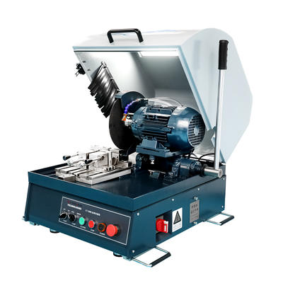
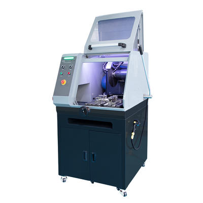
德语CT-250S/CT-250V Manual Sectioning Machine
CT-250S/250V is a manual sectioning machine designed with safety and environmental principles in min...
We use first- and third-party cookies including other tracking technologies from third party publishers to give you the full functionality of our website, to customize your user experience, perform analytics and deliver personalized advertising on our websites, apps and newsletters across internet and via social media platforms. For that purpose, we collect information about user, browsing patterns and device.
By clicking "Accept All Cookies", you accept this, and agree that we share this information with third parties, such as our advertising partners. If you prefer, you can choose to continue with "Only Required Cookies". But keep in mind that blocking some types of cookies may impact how we can deliver tailored content that you might like.
For more information and to customize your options, click on "Cookie settings". If you want to learn more about cookies and why we use them, visit our Cookie Policy page at any time. Cookie Policy

When a quality engineer sees inconsistent tensile strength readings across a single heat-treated batch, one of the first places to look is the grain structure. Grain size measurement is the laboratory procedure that turns those microscopic differences into numbers that can be compared against a standard, tracked over time, and linked to process changes. Whether the goal is verifying a heat treatment cycle, qualifying a new steel supplier, or investigating a service failure, the measurement result is only as trustworthy as the surface being examined.
The starting point is simple to state: grain size measurement determines the average size of the crystallites that make up a metallic material. The practical challenge is that those crystallites cannot be measured on a rough, scratched, or poorly polished specimen. This article explains the main approaches used in metallographic labs, the ASTM E112 framework that governs most work, and the sample preparation steps that determine whether a measurement is meaningful.
Grain size measurement is the quantitative evaluation of the average grain dimensions in a polished and etched metal sample. The term "grain" refers to a single crystal region within the metal, and the boundaries between these regions are revealed by chemical etching or electrolytic polishing. After the microstructure is visible under a microscope, the analyst compares the image with standard charts, counts intercepts along known line lengths, or uses image analysis software to compute an equivalent diameter.
The result is usually expressed as an ASTM grain size number, G. Higher G values correspond to smaller grains. A G of 8 indicates an average intercept length near 22 micrometers, while a G of 4 corresponds to roughly 90 micrometers. The relationship is logarithmic: increasing G by one unit reflects a doubling of the number of grains per unit area under idealized assumptions. This numbering system makes it possible to compare results across laboratories, provided the same preparation and measurement rules are followed.
Grain size is not a cosmetic property. It directly influences mechanical behavior. Finer grains generally produce higher yield strength and better toughness because grain boundaries act as barriers to dislocation motion. Coarser grains tend to improve creep resistance at elevated temperatures, which is why some superalloy applications deliberately aim for larger grain structures. In magnetic steels, grain size affects hysteresis losses. In corrosion-sensitive alloys, excessive grain coarsening can increase susceptibility to intergranular attack.
Because the relationship is material- and application-specific, grain size measurement becomes a qualification tool. A vendor receiving a cast component often specifies a maximum allowable ASTM grain size number. A heat treatment lab uses grain size checks to confirm that an annealing cycle has reached the desired recrystallized structure. A failure analyst compares grain size across a fractured surface and the adjacent undeformed region to see if overheating occurred during service.
ASTM E112, "Standard Test Methods for Determining Average Grain Size," is the most widely referenced procedure in North America and many international markets. It covers several measurement approaches, including the comparison procedure, the planimetric (Jeffries) method, and the intercept (Heyn) method. The standard also includes guidance for anisotropic structures, duplex grain sizes, and non-equiaxed grains.
The comparison procedure is the simplest and most common method. The analyst places the etched specimen under a metallographic microscope and visually matches the field of view against standard charts at a known magnification. This approach requires relatively little measurement time and is adequate for routine quality control when the microstructure is approximately equiaxed and uniform. However, it introduces subjectivity because the operator is making a visual judgment.
The intercept method is more quantitative. A line of known length is superimposed on the image, and the operator counts the number of grain boundaries that cross that line. The average intercept length is computed by dividing the line length by the number of intersections. This technique is less sensitive to grain shape when multiple lines in different directions are used, and it produces data that can be statistically analyzed. The planimetric method counts the number of grains within a known area, which is effective when grain boundaries are fully revealed and the grain size is relatively uniform.
Selection depends on the purpose of the test, the expected microstructure, and the time available. For incoming inspection of a batch of structural steel, the comparison chart method is usually sufficient. For process development where small differences in grain size must be tracked, an intercept count or image analysis routine provides better discrimination. For material qualification in a research program, the planimetric method may be preferred because it produces an area-based average that is easy to report.
Some laboratories use automated image analysis to speed up the process. Software can detect grain boundaries and compute mean grain size distributions, but the results still depend on the quality of the etched surface. If the etching is too light, boundaries are missed. If it is too aggressive, the boundaries are broadened and the software overcounts. So the method choice is only part of the picture.
Grain boundaries are invisible on an as-polished surface. The specimen must be prepared through a sequence of cutting, mounting, grinding, polishing, and etching. Mistakes at any stage can produce artifacts that are later measured as false grains or missed boundaries.
Cutting introduces deformation at the surface. For grain size work, the sectioned surface must be far enough from the original cut zone that the deformed layer is removed during grinding. If a lab cuts a specimen with a cutting wheel that is not appropriate for the material, the affected zone can extend tens of micrometers into the sample, and the grain size measured at that surface will not represent the bulk structure.
Mounting supports the sample during the remaining steps. Hot compression mounting with phenolic resin is standard for routine metals, but for samples that are heat-sensitive or require edge retention, cold mounting with epoxy or acrylic resin is used. The mounting step is more often a practical consideration than a direct source of measurement error, but a poorly mounted sample can rock during polishing and produce uneven material removal.
Grinding removes the deformed layer left by cutting and flattens the surface. Silicon carbide abrasive papers are typically used in a sequence from coarse to fine grit. The practical rule is to grind long enough to remove the damage from the prior step, which often means a longer time at the finest grinding stage than most operators expect. For a steel sample, a common sequence starts at 240 or 320 grit and ends at 1200 grit or finer.
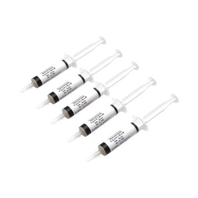
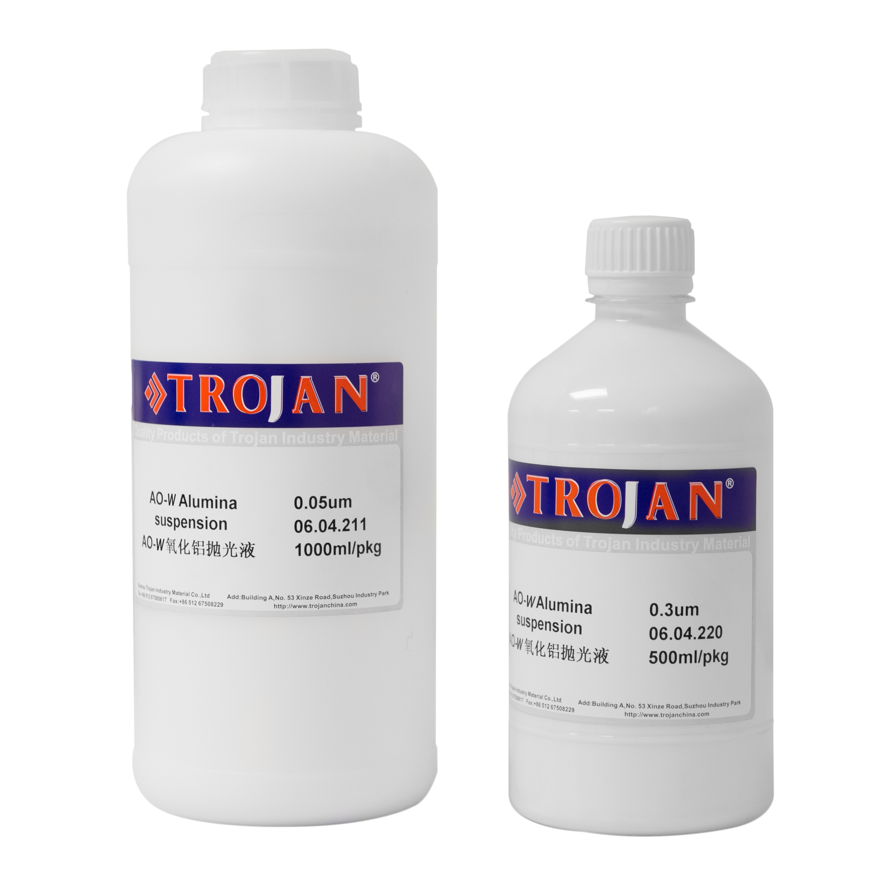
Polishing follows with diamond suspensions on polishing cloths. The goal is a mirror finish with no scratches, no smearing, and no free abrasive particles embedded in the surface. For grain size determination, consistency in polishing quality matters more than achieving the image quality required for photomicrography. Every visible scratch can be mistaken for a grain boundary by either an operator or software, so the polishing sequence should be standardized and verified.
Etching is the final step. The etchant chemistry depends on the alloy system. Nital is common for carbon and low-alloy steels, while Kroll's reagent is used for titanium alloys, and a variety of electrolytic etchants are applied to stainless steels, nickel alloys, and aluminum alloys. The etching time should be long enough to reveal all grain boundaries, but short enough to avoid overetching that produces wide, woolly boundaries. For duplex structures, the analyst must decide whether to measure the smaller phase, the larger phase, or both, and that decision should be documented.
The microscope is the interface between the prepared sample and the final measurement. Its magnification must be selected so that the grain boundaries are clearly resolved, and this magnification must be recorded because the comparison charts are calibrated for specific magnifications.
At lower magnifications, a specimen with ASTM grain size 8 can appear almost featureless, while a specimen with grain size 3 can be evaluated at 100x or even lower. Higher magnifications are useful for finer microstructures, but the depth of field decreases, and illumination uniformity can become an issue. A modern metallurgical microscope with a motorized stage and digital imaging system offers the advantage of capturing multiple fields and building a statistical average from a larger measurement area. This approach reduces the sample-to-sample variability that affects manual measurements.
For routine QC, the comparison method at 100x magnification is widely used for grain sizes G4 through G8. For finer grains, a higher magnification is needed, and the analyst should confirm the effective magnification using a stage micrometer. If the microscope is equipped with a camera and measurement software, the same optical setup can be used for intercept counting, which eliminates the need to print charts and reduces subjective judgment.
Calibration is essential. The magnification must be verified with a certified stage micrometer before comparison or intercept analysis. If the camera's field of view is used as the reference area, the effective area at that magnification must be established mathematically. A small error in magnification is amplified when the result is converted to an ASTM grain size number because the relationship between G and area or intercept length is logarithmic.
Reproducibility is improved when multiple fields are measured. A single field may not represent the average structure of the part. For anisotropic materials, the measurement direction must be defined. Rolling direction, for example, can produce elongated grains, and the measured intercept length will be different parallel and perpendicular to the deformation direction. The standard requires that such anisotropy be reported.
Grain size measurement results are frequently challenged when they do not match the expected values. The cause is usually traceable to a preparation or measurement artifact rather than an actual microstructure anomaly.
Underetching is one of the most common problems. When a grain boundary is only faintly visible, the operator may count it as a boundary in some fields but miss it in others. The resulting grain size number is skewed to a larger value. The same issue occurs when the final polishing step leaves a layer of flowed metal that prevents the etchant from reaching the true boundary network. A single repolish and reetch with a slightly longer time can resolve this.
Overetching broadens grain boundaries into dark bands. Image analysis software may treat a broad boundary as two separate lines, artificially increasing the intercept count and producing a smaller grain size. Visual comparison becomes difficult because the etched surface has low contrast between the boundary and the grain interior. For most metallographic labs, the best approach is to etch a fresh surface and examine it incrementally, stopping at the moment when all boundaries are clearly defined but not significantly widened.
Measurement across multiple fields introduces another source of error when the sample has a duplex grain structure. A bimodal distribution with a few large grains mixed into a fine matrix is not adequately described by a single average value. In such cases, a histogram of intercept lengths or a weighted average should be reported instead of a single ASTM number. This is often the case in dual-phase steels and in deformed and recrystallized structures.
When setting up a grain size measurement capability, the choice of equipment goes beyond the microscope. A typical metallographic laboratory needs a sectioning machine for cutoffs, a mounting press or cold mounting consumables for sample support, a grinder-polisher with appropriate consumables, and a metallurgical microscope with an imaging system.
The microscope is the most visible investment. A basic upright metallurgical microscope with an LED light source and a 5-megapixel camera is sufficient for routine comparison work. If the lab plans to use image analysis software, the microscope needs to be compatible with software that can detect grain boundaries and calculate intercept counts. Some software packages are bundled with the microscope vendor's imaging system, which simplifies integration but may limit flexibility.
Grinding and polishing equipment also affects throughput and consistency. A manual grinder-polisher is flexible and affordable for low volumes, while an automatic grinder-polisher produces more uniform results and reduces operator influence. The tradeoff appears in the purchase price and in the surface quality achieved with strained or soft materials. For a busy lab processing dozens of samples per day, the automatic system is worth the investment because the polishing sequence can be programmed and repeated exactly each time.
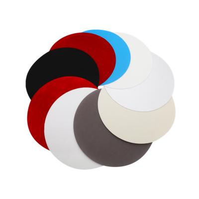
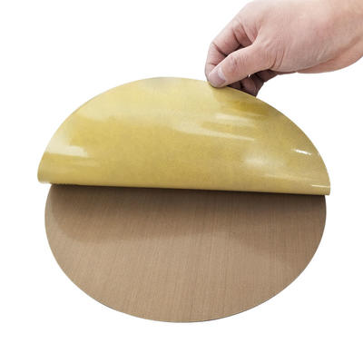
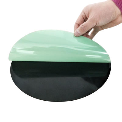
Consumables should not be overlooked. Silicon carbide sandpaper, diamond polishing suspensions, polishing cloths with PSA backing, and etching reagents are all required. The grain size of the abrasive paper and the diamond particle size in the suspension determine the scratch depth left on the final surface. A mismatch between the final grinding step and the first polishing step will extend the polishing time and increase the risk of edge rounding and smearing.
The microscope needs to deliver a flat, evenly illuminated field at the magnification used for comparison. For grain size numbers from G1 to G10, a magnification range between 50x and 500x is usually enough. The objective lens should ideally have a long working distance so that the surface can be inspected without striking the lens, especially when the sample has wedges or a coarse topography.
Routine grain size measurement does not demand the highest numerical aperture, because the resolution required to resolve a boundary is less demanding than the resolution needed to resolve fine inclusions. However, the depth of field must be adequate to keep the entire field in focus across a polished surface. A field-corrected objective designed for metallurgical use is sufficient, and a focusable eyepiece reticle or a calibrated graticule is required if the lab uses the comparison method manually. If a camera is connected to the microscope, the image sensor should deliver sufficient pixel density to display fine grain boundaries without aliasing at the chosen magnification. A camera with at least 3 to 5 megapixels is adequate for most grain size work, while higher resolution is beneficial if high-magnification charts are used.
Software capabilities vary widely. Some packages offer automatic grain boundary detection based on thresholding, while others provide a manual counting tool that lets the operator click on intersection points. The automatic method depends strongly on etching contrast and illumination uniformity. If the lab encounters samples with differing reflectivity or strong color differences, automatic detection may fail, and a manual intercept count may still be needed. A camera and software that include options for both manual and automatic evaluation are more robust.
ASTM E112 defines the primary measurement procedures and has been adopted by many industries. ISO 643 is an international standard for the same purpose, and the two standards are broadly compatible, though they differ in some units and nomenclature. For special materials, additional standards apply. For example, ASTM E930 addresses grain size measurement in isotropic structures, while other specifications cover specific alloys.
When reporting a grain size result, the lab must state the method used, the magnification, the number of fields measured, and the orientation of the section if anisotropic. Without this information, the number has limited meaning. A result reported as "G7 per ASTM E112" is incomplete unless the standard method and the sample location are specified. In many quality systems, the report needs to include the heat number, the sample position, and the surface orientation relative to the original component. This is all part of making the measurement traceable and repeatable.
A complete grain size measurement capability sits within a broader metallography workflow. The sample preparation line can be located in one room and the microscope in another, but the process should be documented as a single chain of custody. A laboratory management system that records preparation parameters, microscope magnification, and software settings helps to identify the source of an unexpected result.
For laboratories that also need hardness testing, the hardness indentation and grain size evaluation can use the same prepared sample. A sample that has been polished and etched for grain size measurement can still be tested for Vickers hardness, provided the etching does not change the near-surface mechanical behavior. For most metals, a light etch has no significant effect on Vickers hardness values, and the hardness testing can be performed after the grain size measurement. This sequence is common in quality labs that produce both grain size and hardness data for a material certification.
The broader point is that grain size measurement is not an isolated activity. It depends directly on the quality of cutting, mounting, grinding, and polishing. It also benefits from a vision system that can capture and archive images. If the lab operates a shared database for images and data, the history of a particular part can be traced through multiple inspections, which is valuable during a failure investigation or an audit.
Grain size measurement is a routine but technically demanding test. The method chosen, the standard used, and the preparation quality all influence the final number. The most reliable approach is to standardize the entire workflow, from cutting through etching, and to verify the microscope's magnification before every measurement session.
For labs setting up this capability, the key purchasing decisions begin with the microscope and extend to the grinding-polishing equipment and consumables. A metallurgical microscope with a calibrated imaging system, an automatic grinder-polisher for reproducible surface preparation, and a well-planned consumables list form the practical foundation for consistent grain size results.

.jpg?imageView2/2/w/400/format/jpg/q/75 "MD-WT Monocrystalline Diamond Suspension")


Based in China, TROJAN pays attention to the international market, and has sold metallographic equipment to more than 50 countries, such as Europe, America, Japan and South Korea, Southeast Asia countries and regions