We use first- and third-party cookies including other tracking technologies from third party publishers to give you the full functionality of our website, to customize your user experience, perform analytics and deliver personalized advertising on our websites, apps and newsletters across internet and via social media platforms. For that purpose, we collect information about user, browsing patterns and device.
By clicking "Accept All Cookies", you accept this, and agree that we share this information with third parties, such as our advertising partners. If you prefer, you can choose to continue with "Only Required Cookies". But keep in mind that blocking some types of cookies may impact how we can deliver tailored content that you might like.
For more information and to customize your options, click on "Cookie settings". If you want to learn more about cookies and why we use them, visit our Cookie Policy page at any time. Cookie Policy
Home / News / Products News / How Precision Sectioning Preserves Structural Integrity in Metallographic Analysis
Home / News / Products News / How Precision Sectioning Preserves Structural Integrity in Metallographic Analysis
How Precision Sectioning Preserves Structural Integrity in Metallographic Analysis
Accuracy Versus Precision: Why the Distinction Matters in Sectioning
In metallurgical sample preparation, accuracy and precision are often used as if they mean the same thing, yet they describe two different qualities of a cut. Accuracy refers to how closely a section matches the intended plane of interest relative to a reference feature, such as a weld centerline or a coating boundary. Precision refers to how repeatable that result is across dozens or hundreds of specimens processed on the same setup. A laboratory can be precise without being accurate, consistently cutting at the wrong angle every time, and it can be accurate on a single sample while lacking the repeatability needed for statistical process control.
This distinction becomes critical the moment a cut is used to judge material performance. A section that drifts even a fraction of a millimeter from the intended plane can misrepresent grain structure, inclusion density, or case-depth measurements. Laboratories that treat accuracy and precision as a single combined goal typically build their sectioning workflow around fixturing, blade selection, and feed control rather than around the cutting motion alone. The remainder of this article works through the mechanical and procedural choices that keep both qualities intact while protecting the microstructure from artificial damage introduced during cutting.
It also helps to separate the two qualities when troubleshooting a failed batch. If measurements are consistently off in the same direction, the problem is usually accuracy, often traced back to a reference edge that was set incorrectly or a fixture that was never verified against the part drawing. If measurements scatter unpredictably from one sample to the next, the problem is usually precision, and it tends to point toward mechanical looseness, inconsistent clamping pressure, or an operator making small manual adjustments between cuts. Diagnosing which category a defect falls into before changing equipment settings saves significant time, since the corrective action for each is different.
Why Structural Integrity Is Compromised During Cutting
Every abrasive cut introduces some disturbance to the material immediately beneath the cut plane. The question is not whether disturbance occurs, but how far it extends and whether it reaches the region a metallurgist actually intends to examine. Three mechanisms account for most of the damage seen in poorly controlled sectioning: frictional heating, mechanical deformation from cutting force, and vibration-induced micro-fracturing.
Frictional heating raises local temperature enough to alter tempering, cause phase transformation in heat-sensitive alloys, or produce a visible burn line at the cut edge.
Mechanical deformation smears surface grains, rounds edges, and can mask the true boundary between a coating and a substrate.
Vibration from an unbalanced wheel or a loosely clamped specimen produces chatter marks that later show up as false features under the microscope.
Because these effects are cumulative, small inefficiencies compound. A wheel that is slightly too aggressive for a given hardness, combined with insufficient coolant flow, does not just slow the cut down; it actively rewrites the microstructure the analyst is trying to observe. Recognizing this early in the workflow is what separates a section that supports a valid conclusion from one that quietly introduces error into a report.
The practical challenge is that damage from cutting is not always visible without further preparation. A burn line hidden beneath the surface can survive coarse grinding and only appear after fine polishing, at which point the sample has already consumed significant preparation time. For this reason, many laboratories treat cutting parameters as part of quality control rather than a separate upstream step, reviewing wheel wear, coolant condition, and feed settings on a fixed schedule rather than only after a defect is discovered downstream.
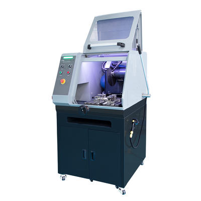
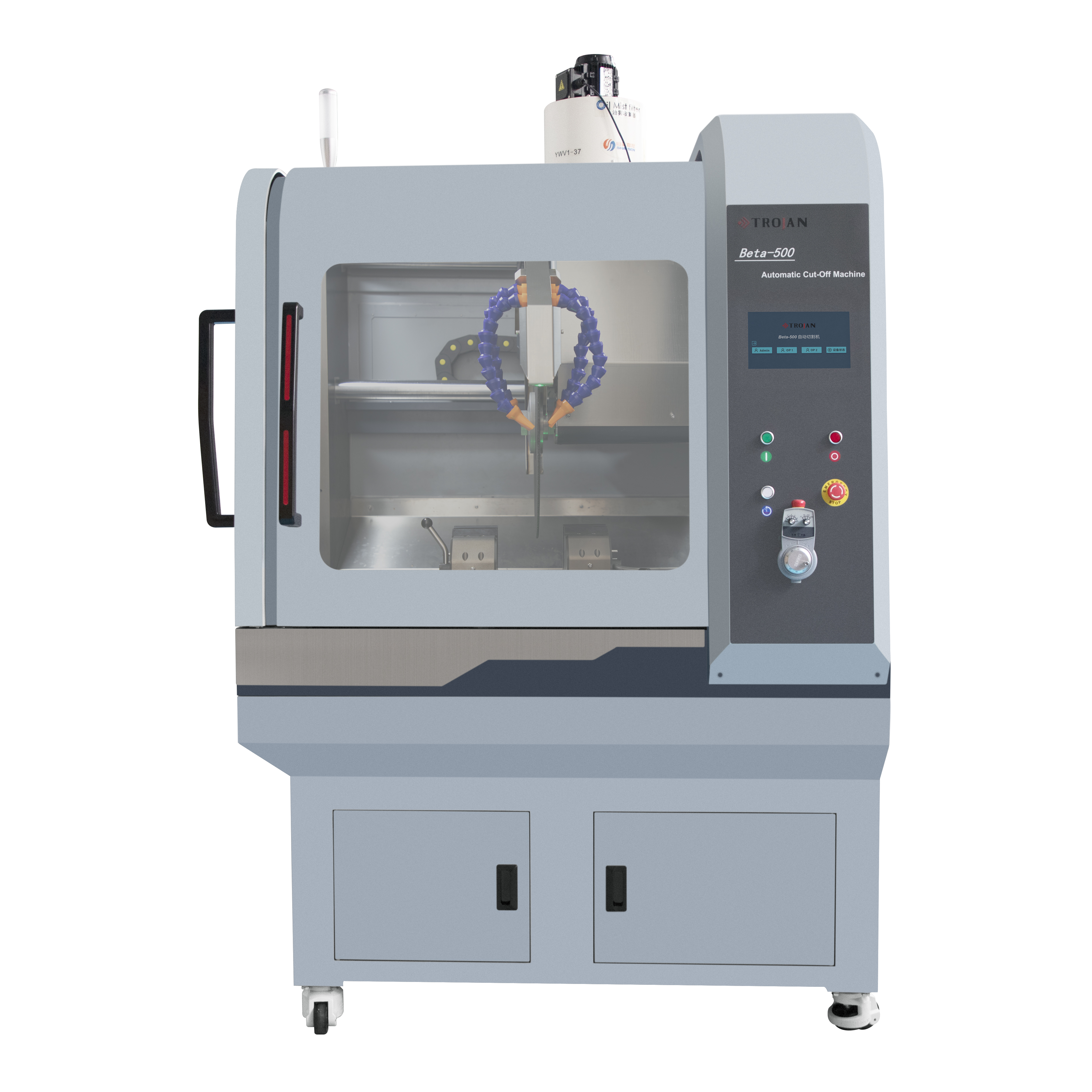
Modern metallographic cutting equipment is built around four subsystems that must work together rather than in isolation: the drive and spindle assembly, the coolant delivery system, the fixturing platform, and the feed control mechanism. Weakness in any one subsystem shows up as damage in the finished section, even if the other three are performing well.
Subsystem
Primary Role
Typical Failure Mode If Underspecified
Spindle and Drive
Maintains consistent rotational speed under load
Speed sag during hard-material cuts, causing uneven heat
Holds the specimen in a fixed, repeatable position
Angular drift, part shift, inconsistent section plane
Feed Control
Regulates the rate at which the blade advances into material
Excess force, edge deformation, wheel glazing
Laboratories evaluating a new cutting station often focus on spindle power alone, which is a reasonable starting point but an incomplete picture. A high-power spindle paired with a weak fixturing platform will simply transmit more vibration into the specimen, not less. The most durable results come from treating the four subsystems as a matched set rather than upgrading one at a time.
Serviceability is another factor that is easy to overlook during initial equipment selection but becomes significant over years of daily use. Blade guards, coolant filters, and drive belts wear at different rates, and equipment designed with accessible service points reduces the downtime associated with routine maintenance. Laboratories running multiple shifts often find that ease of maintenance has a larger effect on total throughput than incremental gains in maximum cutting speed, simply because unplanned downtime affects every sample in the queue rather than just the one being cut.
The defining trait of precision metallographic cutting machines is not raw cutting speed but the ability to hold speed, feed rate, and coolant delivery within a narrow, repeatable band regardless of material hardness. This matters because heat generation during abrasive cutting scales with the interaction between wheel speed, downward force, and contact time, and any single variable drifting out of range shifts the balance toward more heat and more deformation.
Three design features tend to separate machines that hold this balance from those that do not:
Closed-loop speed regulation that compensates for load changes as the blade meets harder or softer regions of a composite or layered sample.
Programmable feed profiles that slow the approach automatically near the exit side of a cut, where breakout damage is most common.
Flood or through-wheel coolant delivery that keeps the cut zone below the temperature at which microstructural changes begin.
For laboratories working with a mix of soft non-ferrous alloys and hardened tool steels in the same week, this consistency matters more than top-end speed. A machine that cuts fast but only performs well within a narrow hardness window forces operators to compensate manually, which reintroduces the variability the equipment was meant to remove.
Coolant chemistry deserves attention alongside the mechanical features of the machine itself. A coolant that lubricates well but drains slowly from the kerf can trap heat rather than remove it, while one that flows freely but lacks sufficient lubricating properties increases friction at the wheel face. Matching coolant concentration and delivery pressure to the wheel type in use, and rechecking that match whenever the wheel is changed, closes a gap that is often left to informal habit rather than a documented setting.
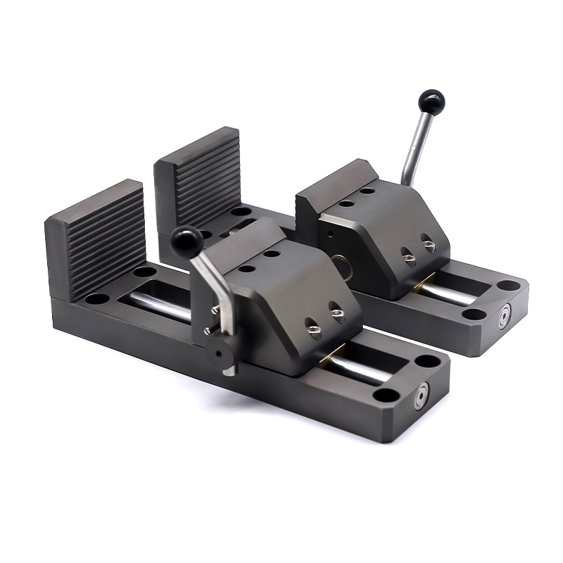
Even a well-specified machine underperforms if the supporting metallographic cutting machine accessories are mismatched to the sample geometry. Fixturing accounts for a large share of preventable sectioning defects, because any part movement during the cut translates directly into an inaccurate or non-repeatable plane.
Vise-style clamps with a wide jaw face distribute clamping force across a larger contact area, which reduces the risk of localized crushing on softer alloys while still holding irregular or angled parts securely. Angle fixtures and V-block holders extend this control to cylindrical or oddly shaped specimens that would otherwise require improvised clamping. Wheel selection accessories, including a range of bond hardness and abrasive grit options, allow a single machine to be matched to a much wider range of material hardness without changing the base equipment.
A practical rule many laboratories follow is to treat fixturing as a per-sample decision rather than a one-time setup. Reviewing fixture fit before each new part geometry takes a few extra minutes but consistently reduces the rate of re-cuts caused by shift during clamping.
Comparing Abrasive Wheel Types Across Key Performance Dimensions
Abrasive wheel selection is one of the few decisions in the sectioning workflow that affects heat generation, edge quality, and cost simultaneously. The chart below compares four common wheel categories across five performance dimensions on a relative scale, based on typical laboratory experience rather than a single vendor specification.
Diamond-bond wheels generally hold an advantage in wear resistance and edge quality, which suits hardened alloys and ceramics where repeated re-truing would otherwise slow throughput. Aluminum oxide wheels remain a practical choice for softer steels and routine production sectioning, where cost efficiency matters more than maximum edge sharpness. Silicon carbide and CBN wheels occupy intermediate positions, each favoring specific material families over general-purpose use.
Wheel bond hardness interacts with the same trade-offs shown in the chart above. A harder bond holds abrasive grains longer, which extends wheel life but can lead to glazing if the material being cut is too soft for that bond grade, since dull grains stay in place rather than releasing to expose fresh cutting edges. A softer bond releases grains more readily, keeping the cutting surface sharp on softer materials at the cost of faster wheel consumption. Laboratories that keep a small inventory of bond grades on hand, rather than standardizing on a single wheel for every job, generally see fewer heat-related defects across a mixed material workload.
Cutting Speed Versus Heat-Affected Zone: Understanding the Trade-off
Increasing cutting speed shortens processing time, but it also tends to increase the depth of the heat-affected zone if coolant flow and feed rate are not adjusted to compensate. The relationship is not linear across the full speed range; most laboratories observe a relatively flat response at lower speeds followed by a sharper increase in heat-affected depth once a material-specific threshold is crossed.
The practical takeaway is that the highest available speed is rarely the correct setting for sensitive alloys. Laboratories that map this curve for their most common materials can identify a working speed just below the inflection point, capturing most of the time savings without pushing the heat-affected zone into the region being examined.
Feed Rate and Deformation Across Material Hardness Categories
Feed rate interacts with material hardness in a way that is easy to underestimate. The same feed setting that produces a clean cut on a mild steel sample can generate visible surface deformation on a softer, more ductile alloy, simply because the material yields rather than shears cleanly under the same force.
Softer, more ductile materials generally require a slower feed and a lighter clamping force to avoid smearing, while harder alloys tolerate a faster feed but demand closer attention to heat buildup. Adjusting feed by hardness category rather than applying a single default setting across all samples is one of the most cost-effective changes a laboratory can make.
Common Sectioning Defects at a Glance
Defect
Likely Cause
Typical Fix
Burn lines at the cut edge
Excess speed or insufficient coolant
Reduce speed, verify coolant flow rate
Angular drift across the section
Loose or mismatched fixturing
Switch to a wider-jaw or angle-specific fixture
Smeared or rounded edges
Excess feed force on ductile material
Lower feed rate, reduce clamping pressure
Chatter marks
Unbalanced wheel or vibration
Re-true or replace wheel, check spindle bearings
A Repeatable Workflow From Sample Selection to Finished Section
Consistency across operators and shifts comes from following the same sequence every time, rather than relying on individual judgment at each step. The flow below outlines a sequence that laboratories commonly use to keep sectioning results comparable across a full production run.
Logging the outcome of each cut, including wheel condition and any deviation from the target plane, closes the loop and gives the laboratory a data trail for identifying slow drift in results before it becomes a rejected batch.
This kind of record keeping tends to feel like extra overhead when a run is going well, but its real value shows up months later when a customer or an internal audit asks why a specific batch of sections differs from an earlier one. Having a dated log of wheel changes, coolant refills, and feed adjustments turns that investigation into a quick lookup rather than a guessing exercise, and it often reveals the slow, gradual drift that no single cut would have flagged on its own.
A Short Checklist Before Every Sectioning Run
Fast production schedules make it tempting to skip verification steps, but a short pre-run check consistently catches the majority of preventable defects before material is wasted.
Confirm wheel type and grit match the material hardness for the current batch.
Check coolant flow and concentration before starting the first cut of the shift.
Verify fixture fit on the actual part rather than assuming it matches the previous batch.
Set feed rate according to the material category, not a single default value.
Inspect the first section under low magnification before proceeding with the full run.
Frequently Asked Questions
Q1: What is the difference between accuracy and precision in sectioning?
Accuracy describes how closely a cut matches the intended plane relative to a reference feature, while precision describes how repeatable that result is across many samples on the same setup.
Q2: Why does cutting speed affect the heat-affected zone?
Higher speed increases the rate of frictional contact between the wheel and the material, and beyond a material-specific threshold this raises local temperature enough to alter the microstructure near the cut edge.
Q3: How often should fixturing be reviewed?
Fixturing should be checked whenever part geometry changes, since a fixture that worked for one shape can allow drift or shift on a differently sized or angled specimen.
Q4: Does a faster feed rate always cause more damage?
Not always. The effect depends heavily on material hardness, with softer and more ductile alloys showing deformation at feed rates that hardened materials tolerate without issue.
Q5: What is the simplest way to reduce chatter marks?
Checking wheel balance and spindle condition before a run addresses the majority of chatter issues, since vibration is usually mechanical in origin rather than a coolant or feed problem.

 英语
英语 西班牙语
西班牙语 德语
德语
.png?imageView2/2/w/400/format/jpg/q/75 "Disposable Sample Cups")

.jpg?imageView2/2/w/400/format/jpg/q/75 "MD-WT Monocrystalline Diamond Suspension")