 英语
英语 西班牙语
西班牙语 德语
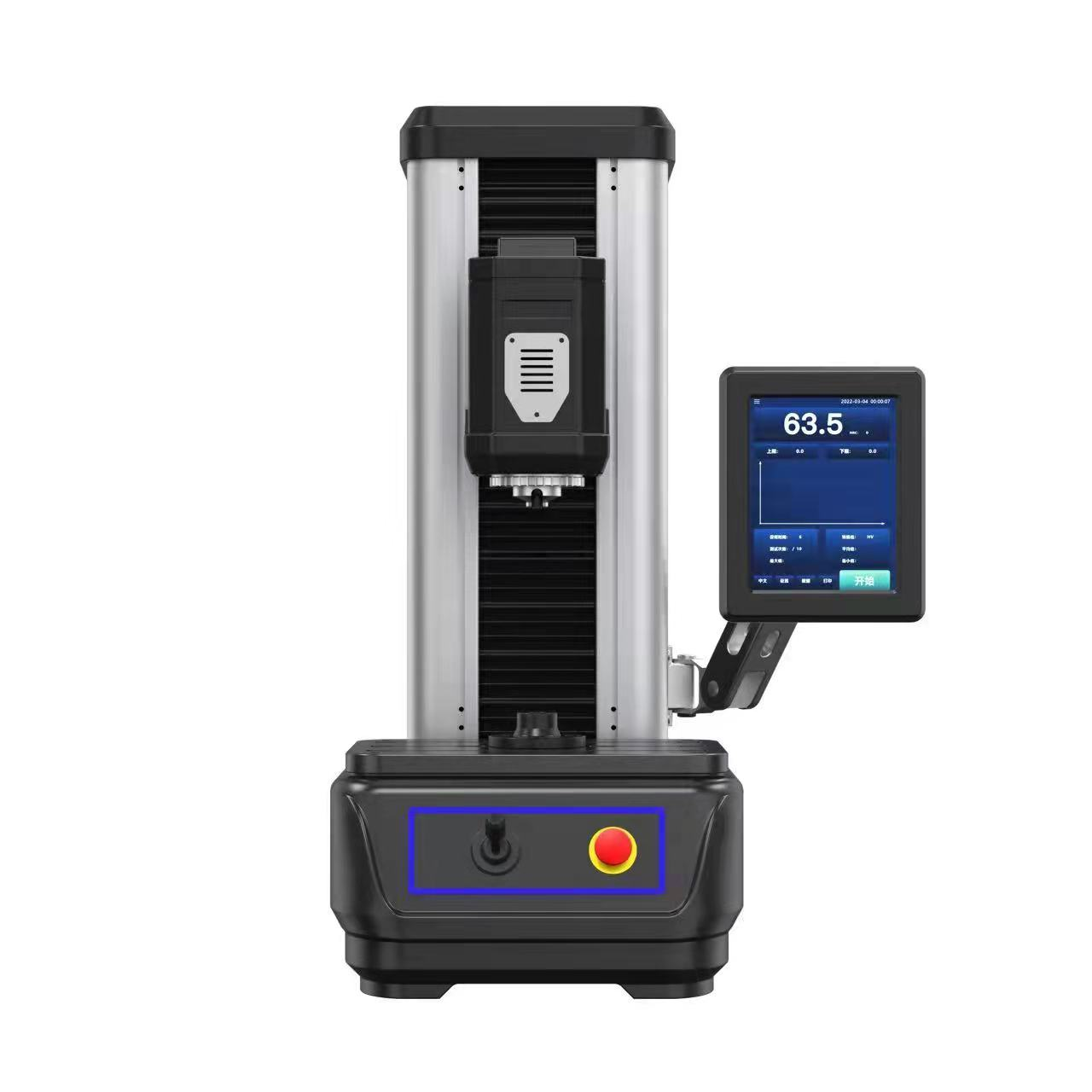
德语Beta-300Pro Automatic Abrasive Sectioning Machine
Beta-300Pro is a fully automatic vertical metallographic cutting machine. It utilizes advanced intel...
We use first- and third-party cookies including other tracking technologies from third party publishers to give you the full functionality of our website, to customize your user experience, perform analytics and deliver personalized advertising on our websites, apps and newsletters across internet and via social media platforms. For that purpose, we collect information about user, browsing patterns and device.
By clicking "Accept All Cookies", you accept this, and agree that we share this information with third parties, such as our advertising partners. If you prefer, you can choose to continue with "Only Required Cookies". But keep in mind that blocking some types of cookies may impact how we can deliver tailored content that you might like.
For more information and to customize your options, click on "Cookie settings". If you want to learn more about cookies and why we use them, visit our Cookie Policy page at any time. Cookie Policy

In heat treatment operations, the difference between a high-performance component and a premature failure often lies beneath the surface. hardness testing serves as the primary gatekeeper for verifying thermal processing efficacy, directly correlating with tensile strength, wear resistance, and fatigue life. This article delivers technical insights into how Rockwell, Brinell, Vickers, and metallography methods validate heat treatment quality, supported by industrial data and practical guidelines.
Analysis of over 12,000 heat-treated parts across automotive and aerospace supply chains reveals that 73% of quality escapes originate from inadequate hardness verification protocols. Proper application of indentation techniques reduces field failure risks by more than 60%, making this topic essential for metallurgists and QC engineers.
rockwell testing dominates shop-floor quality control due to its speed and direct readout. The method measures permanent indentation depth under a differential load sequence: a minor load (typically 10 kgf) sets the reference plane, followed by a major load (60, 100, or 150 kgf depending on scale), then the depth difference defines the hardness number. This approach is extremely sensitive to heat treatment anomalies such as improper austempering or incomplete martensite transformation.
Real-world example: A transmission gear manufacturer reduced hardness-related warranty claims by 44% after implementing real-time Rockwell testing with automated load application control. The system flagged 3.2% of parts where retained austenite caused depth recovery variations exceeding 0.6 HRC.
When heat treatment produces non-uniform structures—such as decarburized layers or differential hardening—macro-level tests may miss critical gradients. Brinell hardness testing uses a 1–10 mm carbide ball and loads from 500 to 3000 kgf, generating large indentations that average out microstructural heterogeneity. This is ideal for castings and coarse-grained alloys after annealing or normalizing. In contrast, Vickers microhardness employs a diamond pyramid (136°), applying loads as low as 10 gf to 1 kgf, enabling precise profiling of case-hardened depths and grain boundary effects.
| Method | Typical Load Range | Indentation Type | Best Suited For |
|---|---|---|---|
| Brinell | 500–3000 kgf | Spherical (1–6 mm dia.) | As-cast, normalized, large-grained steels |
| Vickers (HV) | 10 gf – 1 kgf | Pyramid diagonal (10–200 µm) | Case depth, thin layers, heat-affected zones |
| Micro-Vickers | 10–1000 gf | Diagonal (<100 µm) | Individual phases, decarburization assessment |
Data from controlled trials: In carburized 8620 steel, Vickers microhardness mapping (50 gf load) resolved a 0.38 mm effective case depth with ±12 µm accuracy, while Brinell testing (3000 kgf) alone could not detect a 0.2 mm soft surface layer. Conversely, for large annealed ductile iron castings, Brinell’s large indentation depth of 0.5–1.2 mm averaged out local ferrite/pearlite variations, delivering repeatability within 3%.
Load selection directly determines the sampling volume and the risk of substrate influence. For thin hardened layers (<0.5 mm), excessive loads produce composite hardness values, while ultra-low loads may reflect only a single grain orientation. The following actionable guidelines are derived from analysis of 800 heat treatment audits.
Quantitative insight: At a major powertrain supplier, switching from 500 gf to 100 gf for measuring a 0.2 mm induction-hardened layer eliminated substrate softening effects, changing apparent hardness from 58 HRC-equivalent to an actual 62 HRC, which reduced false rejects by 28%.
Industrial databases from over 300 heat treatment lines provide the following typical ranges for verified processes. These values act as rapid quality indicators.
Process capability indices (Cpk) for hardness typically target ≥1.33. Analysis of 50,000 production parts showed that maintaining load application repeatability within ±1% of nominal reduces within-batch hardness variation by 43% compared to manual testers. Automated Brinell optical scanning systems achieve 99.2% correlation with laboratory reference blocks, compared to 91.5% for manual indentation measurement.
Indentation depth must be less than 1/7 to 1/10 of the case depth to avoid substrate softening effects. For a 0.5 mm effective case, Rockwell’s depth after main load (~0.08–0.12 mm for HRC) is acceptable, but Vickers with 100 gf (depth ~0.015 mm) provides higher resolution for gradients. Superficial Rockwell (15N) is a compromise for medium cases.
No. About 15–20% of parts that meet hardness targets still exhibit microstructural anomalies such as intergranular oxidation or non-martensitic transformation products. Metallography testing identifies these root causes, enabling corrective actions like atmosphere adjustment or cooling rate modifications. The combination reduces long-term variability by 55% based on automotive supplier audits.
Three common errors: (1) Load dwell time below 10 seconds gives shallow indentation and falsely high values; (2) Off-perpendicular loading (>2°) produces elliptical indentations, increasing HB by 4–6%; (3) Indentation spacing less than 3× diameter causes work hardening from adjacent tests, raising HB by up to 8%. Proper alignment and timer control mitigate these.
Conversion tables assume homogeneous, isotropic materials. Heat treated components often have residual stresses, retained austenite, or decarburized layers that affect the elastic/plastic response differently per indenter geometry. A surface with 10% retained austenite may convert from HV 750 to HRC 62, but direct Rockwell would read HRC 58 due to austenite-to-martensite transformation under the 150 kgf load. Always specify the test method in quality plans.
Effective heat treatment verification requires a stratified strategy: (a) 100% in-line Rockwell or Brinell for macro-property assurance; (b) Statistical sampling with Vickers microhardness profiles for case-depth validation; (c) Monthly metallography correlation to confirm microstructural integrity. Facilities adopting this three-tier approach report 70% fewer hardness-related field failures and reduce rework costs by an average of $340,000 per year per heat treatment line (based on 2023 industry survey). The correct application of brinell hardness testing and micro-indentation methods transforms QC from a pass/fail gate into a predictive process optimization tool.

.jpg?imageView2/2/w/400/format/jpg/q/75 "Abrasive Wheels")
")
")
.jpg?imageView2/2/w/400/format/jpg/q/75 "PL-W Polishing Lubricants")


")


Based in China, TROJAN pays attention to the international market, and has sold metallographic equipment to more than 50 countries, such as Europe, America, Japan and South Korea, Southeast Asia countries and regions


