
 英语
英语 西班牙语
西班牙语 德语
德语Beta-300Pro Automatic Abrasive Sectioning Machine
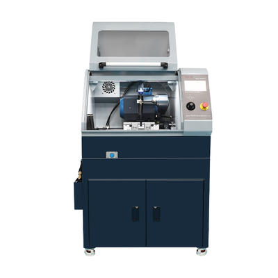
Beta-300Pro is a fully automatic vertical metallographic cutting machine. It utilizes advanced intel...
We use first- and third-party cookies including other tracking technologies from third party publishers to give you the full functionality of our website, to customize your user experience, perform analytics and deliver personalized advertising on our websites, apps and newsletters across internet and via social media platforms. For that purpose, we collect information about user, browsing patterns and device.
By clicking "Accept All Cookies", you accept this, and agree that we share this information with third parties, such as our advertising partners. If you prefer, you can choose to continue with "Only Required Cookies". But keep in mind that blocking some types of cookies may impact how we can deliver tailored content that you might like.
For more information and to customize your options, click on "Cookie settings". If you want to learn more about cookies and why we use them, visit our Cookie Policy page at any time. Cookie Policy

A metallurgical sample can only reveal what its surface allows. Scratches, smeared grain boundaries, or embedded abrasive particles distort every image captured afterward, regardless of how advanced the optical or electron equipment is. metallographic grinding & polishing is the stage where a rough-cut specimen is transformed into a flat, deformation-free surface suitable for structural analysis.
Laboratories that treat this stage as a formality often spend far more time troubleshooting inconsistent micrographs later. A disciplined sequence, matched abrasive selection, and correct pressure control typically resolve more than 80 percent of surface-related imaging complaints reported in routine lab audits.
Rule of thumb used across many metallography labs: each grinding step should remove all scratches from the previous step before moving forward, never the reverse.
Not every microscopy technique requires the same level of surface refinement. Choosing a preparation route without considering the intended imaging method wastes both abrasive consumables and operator time.
| Microscopy Type | Typical Surface Roughness Target | Sensitivity to Scratches | Common Application |
|---|---|---|---|
| Optical (bright field) | Ra below 0.05 micrometers | High | Grain size, phase distribution |
| Optical (dark field / DIC) | Ra below 0.03 micrometers | Very high | Surface topography contrast |
| Scanning electron microscopy | Ra below 0.02 micrometers | Very high | Fractography, fine microstructure |
| Electron backscatter diffraction | Near-mirror, deformation-free | Extreme | Crystallographic orientation mapping |
| Stereo / macro inspection | Ra 0.1 to 0.3 micrometers | Low to moderate | Weld or casting overview |
The stricter the imaging requirement, the more grinding and polishing steps are typically needed to remove the deformation layer left by the previous stage.
A typical metallographic workflow moves through four broad phases: sectioning, mounting, grinding, and polishing. The diagram below outlines how material removal rate decreases while surface finish improves at each stage.
Each transition should reduce scratch depth by roughly one order of magnitude. Skipping a grit step forces the next stage to work far longer, which raises the risk of overheating and unwanted relief between hard and soft phases.
Grinding uses bonded or coated abrasives to remove saw marks and flatten the specimen. The consumable choice at this stage directly affects both cycle time and final flatness.
Choosing the correct metallographic grinding papers & foils for the material hardness prevents premature abrasive breakdown and keeps material removal consistent across a batch of samples.
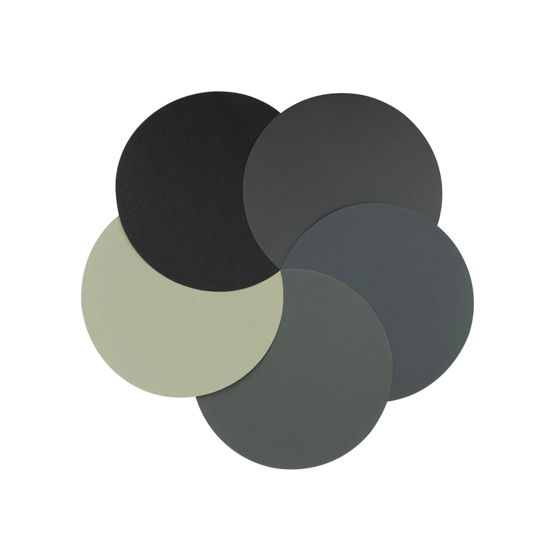
Silicon carbide papers and diamond-coated foils used across grinding stages
| Property | Silicon Carbide Paper | Diamond Foil |
|---|---|---|
| Wear rate | Faster, needs frequent replacement | Slower, longer usable life |
| Cutting consistency | Decreases as grit wears | Stays stable through most of its life |
| Best suited for | Soft to medium alloys, high sample volume | Hard, brittle, or coated materials |
Polishing removes the fine deformation layer left by grinding using abrasive suspensions on cloth-covered platens. Suspension particle size, cloth nap, and lubricant chemistry each influence the final result independently.
Cloth nap height controls how much relief develops between phases of different hardness. Low nap cloths hold flatness well but cut slowly; high nap cloths remove material faster but risk rounding edges and inclusions.
Lubricants carry the abrasive, dissipate frictional heat, and prevent particle embedding. Water-based lubricants suit most ferrous alloys, while oil-based or alcohol-based carriers are typically chosen for water-sensitive or porous materials to avoid staining and corrosion during preparation.
Manual preparation depends heavily on operator technique, which introduces variability between samples and between operators. metallographic grinding & polishing machines address this by controlling platen speed, applied force, and cycle time within fixed parameters.
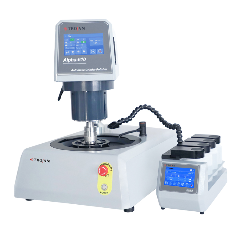
A semi-automatic preparation platform used for grinding and polishing cycles
| Parameter | Typical Range | Effect on Result |
|---|---|---|
| Platen speed | 150 to 600 rpm | Higher speed increases removal rate but raises heat generation |
| Applied force per sample | 10 to 30 newtons | Excess force causes deformation and edge rounding |
| Cycle time per stage | 60 to 300 seconds | Longer cycles risk overpolishing soft phases |
| Rotation direction | Same or contra rotation | Contra rotation often improves scratch uniformity |
Batch holders that process several specimens simultaneously improve throughput and reduce the influence of individual hand pressure, which matters most for laboratories running standardized quality control programs.
Visual inspection under raking light can catch obvious scratch patterns, but quantitative roughness measurement gives a more defensible result for quality documentation.
| Indicator | What It Suggests | Likely Cause |
|---|---|---|
| Directional scratch lines under light | Previous grit not fully removed | Insufficient time or pressure at the prior stage |
| Comet-tail marks near inclusions | Particle pull-out during polishing | Cloth too aggressive for the phase hardness present |
| Rounded edges near the sample border | Edge retention failure | Soft mounting material or excessive polishing time |
| Dull, hazy reflection | Incomplete final polish | Contaminated suspension or worn cloth |
Most laboratories use three to four grinding steps, moving from coarse to fine grit, before transitioning to diamond suspension polishing. Harder or more scratch-sensitive materials may require an additional intermediate step.
This usually means an earlier grinding stage was not fully completed, leaving deeper scratches that later fine stages cannot remove within a reasonable cycle time. Returning to the previous grit and extending that step often resolves it.
Edge rounding typically results from a mismatch in hardness between the mounting material and the sample, combined with excessive polishing pressure or time near the sample boundary.
Not always. Manual preparation can produce excellent results with trained operators and consistent technique, but automated platforms improve repeatability when sample volume or reporting requirements increase.
Replacement depends on usage intensity, but a cloth showing glazing, compaction, or reduced cutting efficiency should be replaced rather than pushed further, since a worn cloth increases the risk of relief and scratch inconsistency.

.jpg?imageView2/2/w/400/format/jpg/q/75 "MD-WT Monocrystalline Diamond Suspension")

Based in China, TROJAN pays attention to the international market, and has sold metallographic equipment to more than 50 countries, such as Europe, America, Japan and South Korea, Southeast Asia countries and regions


