
 英语
英语 西班牙语
西班牙语 德语
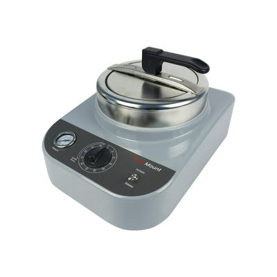
德语ThetaMount Pressure Cold Mounting Machine
Product Description
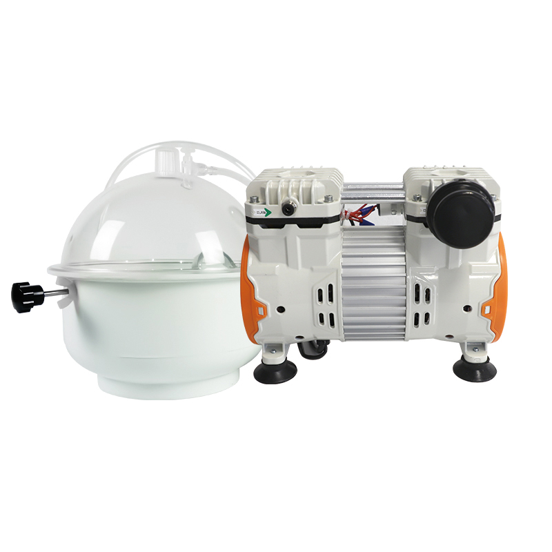
ThetaMount Pressure Cold Machine features a compact design with a maximum pressu...
We use first- and third-party cookies including other tracking technologies from third party publishers to give you the full functionality of our website, to customize your user experience, perform analytics and deliver personalized advertising on our websites, apps and newsletters across internet and via social media platforms. For that purpose, we collect information about user, browsing patterns and device.
By clicking "Accept All Cookies", you accept this, and agree that we share this information with third parties, such as our advertising partners. If you prefer, you can choose to continue with "Only Required Cookies". But keep in mind that blocking some types of cookies may impact how we can deliver tailored content that you might like.
For more information and to customize your options, click on "Cookie settings". If you want to learn more about cookies and why we use them, visit our Cookie Policy page at any time. Cookie Policy

Every hardness number on a material certificate traces back to a single mechanical event: a hard indenter is pressed into a surface under a controlled load, and the material's resistance to permanent deformation is converted into a value. That value only means something if the load, the indenter geometry, the dwell time, and the measurement technique are all held to a known standard. This is the core discipline behind metallographic hardness testing, where the goal is not just to produce a number but to produce a number that another lab, another shift, or another country can reproduce within a tight tolerance band.
At the microstructural level, hardness is a proxy for several underlying mechanical properties: yield strength, work hardening behavior, and in some cases wear resistance. A martensitic steel and an annealed aluminum alloy respond to the same indenter in completely different ways, which is why no single testing method covers every material, thickness, and surface condition equally well. Selecting the right method, and running it correctly, is what separates a defensible quality record from a number that looks precise but carries no real traceability.
Load application is not a single push. In most modern testers the indenter is first brought into contact with the surface under a small preliminary load, which seats the indenter and removes surface irregularities from the measurement. The major load is then applied at a controlled rate, held for a specified dwell period, and released in a defined sequence. Rushing this sequence, or letting vibration disturb the frame during dwell, is one of the most common sources of scatter in a hardness lab, often larger than any error introduced by the indenter itself.
Dwell time matters because materials creep slightly under sustained load. A test held for too short a period may read artificially high, while excessive dwell on soft or coated materials can produce a reading that no longer represents the bulk property being investigated. Controlling load rate, dwell time, and unloading rate to a documented tolerance is what allows results from different testers to be compared with confidence.
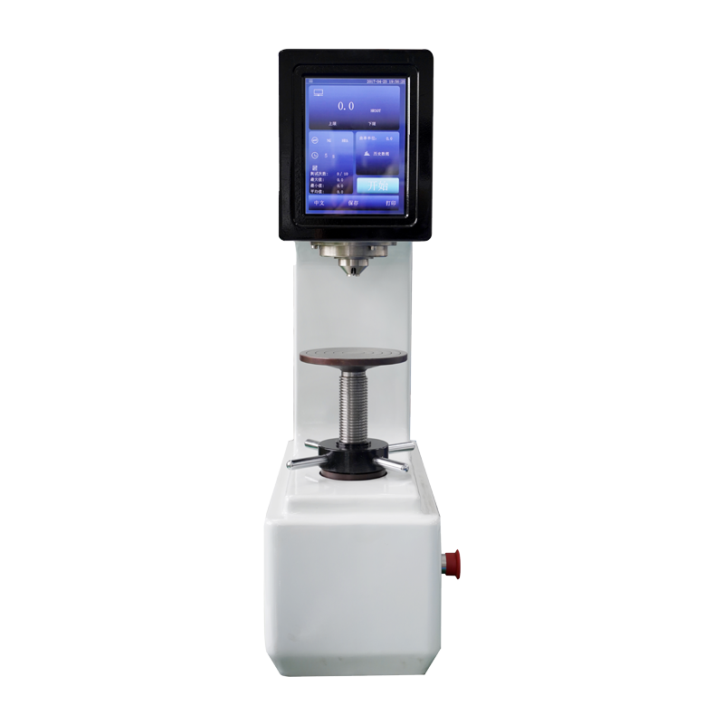
The Rockwell method skips optical measurement entirely. Instead of measuring the size of an indentation, rockwell hardness testers apply a small preliminary load, zero the depth reading, apply the major load, then release back to the preliminary load and read the difference in indentation depth. That depth differential is converted directly into a hardness number on the machine's display, which is why Rockwell testing is often the fastest of the three methods in a production environment.
Scale selection depends on the indenter type and load combination. A diamond cone indenter under a 150 kgf major load is typical for hardened steels, while a hardened steel ball indenter under a 100 kgf load suits softer metals such as annealed steel, brass, or aluminum alloys. Because the result reads out immediately without an operator interpreting an optical image, Rockwell testing is well suited to incoming material inspection, heat treatment verification, and high-volume production checks where consistency between operators matters as much as raw precision.
The trade-off is sensitivity to surface condition. Because the method relies on depth rather than area, rough surfaces, thin sections, or curved parts can distort the reading unless proper correction factors and minimum thickness guidelines are followed.
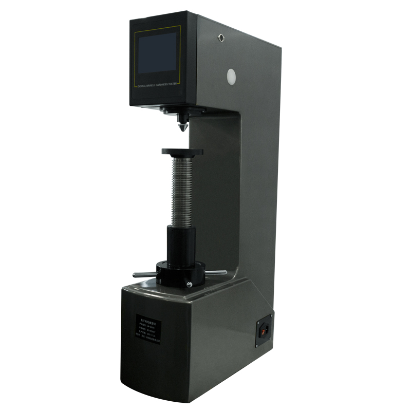
Where Rockwell reads depth, brinell hardness testers press a hardened steel or tungsten carbide ball into the surface under a heavy load, sustained for a set dwell period, then measure the diameter of the resulting indentation under magnification. Because the indentation is large relative to grain size, Brinell testing effectively averages across coarse or non-uniform microstructures, which makes it the preferred method for castings, forgings, and materials where localized grain boundaries or inclusions could distort a smaller indentation.
Loads in Brinell testing commonly range from a few hundred to three thousand kgf, applied through a ball that may be several millimeters in diameter. This produces an indentation large enough to see with the naked eye in many cases, though accurate diameter measurement still requires a calibrated microscope or digital measuring system. The scale is well matched to thick sections, raw stock, and heat-treated components where a bulk hardness value is more meaningful than a highly localized reading.
Because the indentation is large, Brinell testing is generally unsuitable for thin parts, coated surfaces, or finished components where a visible mark is not acceptable, which is where the other two methods take over.
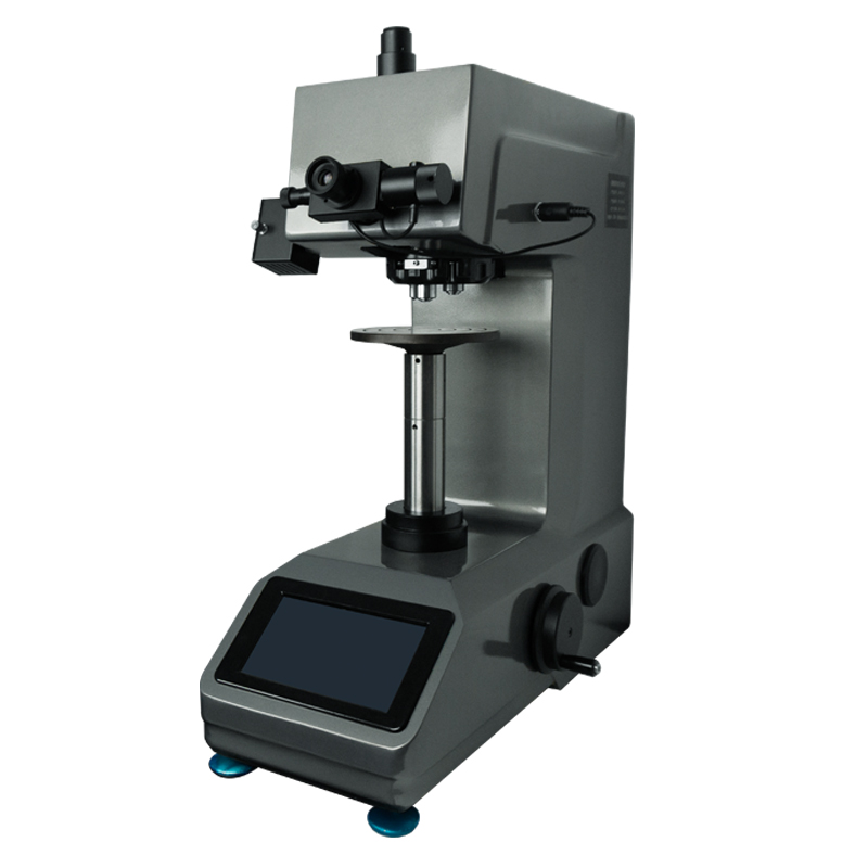
Vickers & micro-vickers hardness testers use a pyramidal diamond indenter that produces a small square indentation regardless of load, which is measured optically by both diagonals under magnification. Because the same indenter geometry is used across the entire load range, from macro Vickers loads down to micro loads well under one kgf, the method scales cleanly from bulk material testing down to individual grains, weld heat-affected zones, and coating cross-sections only a fraction of a millimeter thick.
Micro-Vickers testing in particular is the method of choice for case-hardened layers, nitrided surfaces, plated coatings, and hardness gradient mapping across a polished cross-section. Because the indentation size can be kept extremely small, a single sample can carry dozens of individual readings without the indentations overlapping or interfering with each other, allowing a full hardness profile to be built from surface to core.
The precision comes at a cost of speed and sample preparation. Accurate diagonal measurement requires a well-polished, flat surface and a trained operator or calibrated image analysis system, since even small focus or lighting errors can shift the measured diagonal enough to change the reported hardness.
No single scale is universally correct. The table below summarizes the practical differences that typically decide which method is used on a given part or material.
| Attribute | Rockwell | Brinell | Vickers / Micro-Vickers |
|---|---|---|---|
| Indenter type | Diamond cone or steel ball | Steel or carbide ball | Diamond pyramid |
| Measurement basis | Depth differential | Indentation diameter | Indentation diagonal |
| Typical load range | 60-150 kgf | 500-3000 kgf | 0.1-50 kgf |
| Best suited to | Production line checks | Castings and coarse grain stock | Coatings and thin sections |
| Operator dependence | Low | Moderate | Higher |
A hardness tester is only as trustworthy as its last verification. Certified reference blocks with a known, traceable hardness value are used to check a tester's accuracy at regular intervals, and the deviation between the tester's reading and the block's certified value is logged over time. Internationally recognized material testing standards define the tolerance bands for this deviation, the frequency of verification, and the documentation required to keep a tester in service for regulated or audited work.
Drift is rarely sudden. It tends to creep in gradually as an indenter wears, a load cell ages, or an optical measurement system falls slightly out of calibration. Tracking deviation across successive verification cycles, rather than relying on a single pass or fail result, gives a much earlier warning that maintenance is needed.
Method selection generally comes down to three questions: how coarse or uniform the microstructure is, how thin or coated the section under test is, and how many parts need to be checked per shift. A simple decision path covers most real-world cases.
Throughput is often the deciding factor once precision requirements are met. Rockwell testing typically processes the highest number of parts per hour because the depth reading is automatic, Vickers and micro-Vickers fall in the middle depending on how many indentations are needed per sample, and Brinell is generally the slowest due to the optical diameter measurement and larger indentation.
Yes, provided the surface area allows separate indentation zones. Many labs use Rockwell for a fast production check and follow up with Vickers on a cross-section when a detailed hardness gradient is needed near a heat-treated or coated surface.
Each method measures a different physical response, depth, diameter, or diagonal length, under a different load and indenter geometry. Conversion tables exist for some material families, but they are approximations rather than exact equivalents, and results reported on the original scale are always more reliable.
Verification frequency depends on usage volume, the criticality of the parts being tested, and the requirements of the relevant material testing standard the lab operates under. High-volume production testers are typically checked more frequently than testers used for occasional laboratory work.
The indentation left by micro-Vickers testing is extremely small, which makes it a common choice for quality checks on finished parts where surface marking must be minimized, though acceptance criteria should still confirm the indentation does not affect part function.
Inconsistent surface preparation and operator variation in optical measurement are the two most common sources of scatter, followed by improper load application timing and indenter wear that has not been caught by routine calibration checks.
.png?imageView2/2/w/400/format/jpg/q/75 "Disposable Sample Cups")

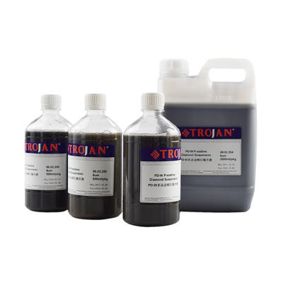
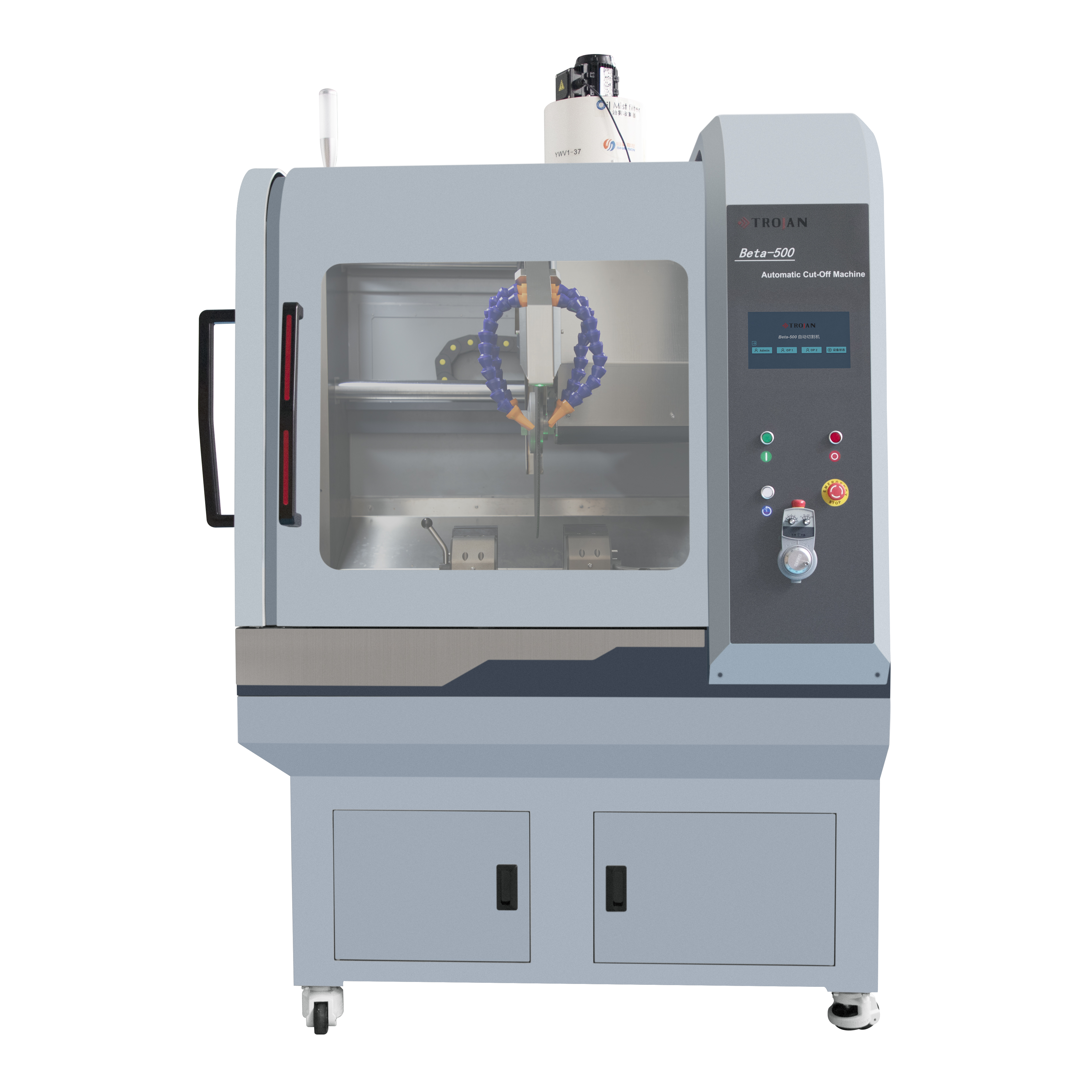

Based in China, TROJAN pays attention to the international market, and has sold metallographic equipment to more than 50 countries, such as Europe, America, Japan and South Korea, Southeast Asia countries and regions


